Tenstorrent Wormhole Series Part 2: Which disabled rows?
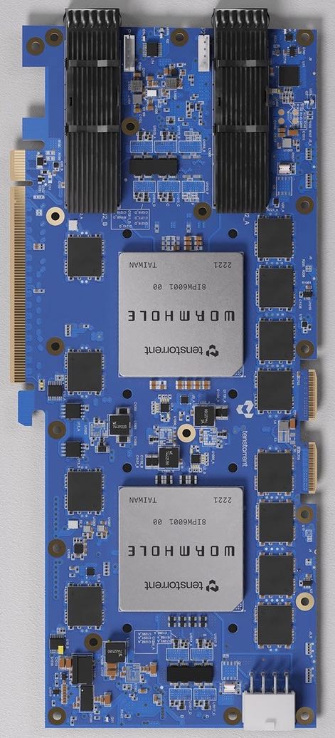
Previously, we considered the physicalities of a Tenstorrent Wormhole card, ending on the remark that one or two rows of T tiles will be disabled in every chip shipped to customers. That naturally begs the question: if you're a customer with a chip (like me), how do you determine which rows are disabled?
It should be noted that most people shouldn't need to care about this question, as a combination of various Tenstorrent-provided software layers should successfully abstract away this difference. That said, I'm not most people; I want to characterise and understand how these cards work at a very low level. Consequently, I'm going to be ignoring most of the Tenstorrent-provided software layers; the kernel-mode driver is fine, and some closed-source firmware is unavoidable at the moment, but I'll ignore the user-mode driver along with all of TT-NN/TT-Metalium and TT-Buda. Again, if you are most people, you probably want to be using those software layers rather than doing what I'm about to do.
Opening the kernel driver is simple enough:
int fd = open("/dev/tenstorrent/0", O_RDWR | O_CLOEXEC);
ASSERT(fd >= 0);
We can then ask the kernel driver what memory ranges (i.e. PCIe bars) it has available for mapping:
#define TENSTORRENT_IOCTL_QUERY_MAPPINGS 0xFA02

struct tenstorrent_mapping {
  uint32_t mapping_id;
  uint32_t reserved;
  uint64_t mapping_base;
  uint64_t mapping_size;
};

#define TENSTORRENT_MAPPING_RESOURCE0_UC 1
#define TENSTORRENT_MAPPING_RESOURCE0_WC 2
#define TENSTORRENT_MAPPING_RESOURCE2_UC 5

unsigned char resource_to_mapping[8] = {0};
struct tenstorrent_mapping mappings[sizeof(resource_to_mapping) + 1];
mappings[0].mapping_size = sizeof(resource_to_mapping);
ASSERT(ioctl(fd, TENSTORRENT_IOCTL_QUERY_MAPPINGS, &mappings[0].mapping_size) >= 0);
mappings[0].mapping_size = 0;
for (unsigned i = 1; i <= sizeof(resource_to_mapping); ++i) {
  uint32_t resource = mappings[i].mapping_id;
  if (resource < sizeof(resource_to_mapping)) {
    resource_to_mapping[resource] = i;
  }
}
To make some future things easier, I want to map these resources in a very particular way:
- The first 464MB of resource 0, as write-combining memory.
- Then the next 32MB of resource 0, as uncacheable memory.
- Then the middle/final 16MB of resource 2, as uncacheable memory.
This sums to a neat 512MB, so it needs one mmap call to reserve a contiguous 512MB range of virtual address space, followed by one mmap call per resource range. If resource 0 isn't available as WC, or less than 464MB is available as WC, then mapping it as uncacheable is an acceptable fallback:
#define BAR0_WC_SIZE (464 << 20)
#define BAR0_SIZE    (496 << 20)
#define MMAP_SIZE    (512 << 20)

#define BAR4_SOC_TARGET_ADDRESS 0x1E000000

struct tenstorrent_mapping* bar0uc = mappings + resource_to_mapping[TENSTORRENT_MAPPING_RESOURCE0_UC];
struct tenstorrent_mapping* bar0wc = mappings + resource_to_mapping[TENSTORRENT_MAPPING_RESOURCE0_WC];
struct tenstorrent_mapping* bar4uc = mappings + resource_to_mapping[TENSTORRENT_MAPPING_RESOURCE2_UC];
ASSERT(bar0uc->mapping_size >= BAR0_SIZE);
ASSERT(bar4uc->mapping_size >= MMAP_SIZE - BAR4_SOC_TARGET_ADDRESS);

char* dev = mmap(NULL, MMAP_SIZE, PROT_NONE, MAP_PRIVATE | MAP_ANONYMOUS, -1, 0);
ASSERT(dev != MAP_FAILED);

uint32_t wc_size = bar0wc->mapping_size;
if (wc_size) {
  if (wc_size > BAR0_WC_SIZE) {
    wc_size = BAR0_WC_SIZE;
  }
  if (mmap(dev, wc_size, PROT_READ | PROT_WRITE, MAP_SHARED | MAP_FIXED, fd, bar0wc->mapping_base) == MAP_FAILED) {
    wc_size = 0;
  }
}
ASSERT(mmap(dev + wc_size, BAR0_SIZE - wc_size, PROT_READ | PROT_WRITE, MAP_SHARED | MAP_FIXED, fd, bar0uc->mapping_base + wc_size) != MAP_FAILED);
ASSERT(mmap(dev + BAR0_SIZE, MMAP_SIZE - BAR0_SIZE, PROT_READ | PROT_WRITE, MAP_SHARED | MAP_FIXED, fd, bar4uc->mapping_base + (BAR0_SIZE - BAR4_SOC_TARGET_ADDRESS)) != MAP_FAILED);
This gives us a 512MB window for talking to the Wormhole ASIC, but what wonders does this window contain? It so happens that the 16MB from resource 2 contains an assortment of configuration registers on the ARC and PCIe tiles. Meanwhile, the remainder of the window maps to the PCIe tile, and any read/write performed by the host against this window gets translated into a NoC read/write by the PCIe tile. The details of that translation can be tweaked by using some configuration registers in the aforementioned resource 2. The general shape cannot be tweaked: the 496MB range subdivides into 156 pieces of size 1MB, 10 pieces of size 2MB, and 20 pieces of size 16MB. After that, things get tweakable: for each piece, we can specify the X/Y coordinates of the tile on the NoC to read/write (or the X/Y coordinates of a rectangular range of tiles for multicast writes), which 1MB/2MB/16MB-aligned range of address space within the tile to target, whether to use NoC #0 or #1, and a few other properties. The Tenstorrent software calls these pieces TLBs, which is not to be confused with the TLB used within a CPU to translate between virtual and physical addresses. Mapping the first 464MB of resource 0 as write-combining means that most of the pieces are write-combining; only the final two 16MB pieces fall within the uncacheable part (note that this WC/UC difference only affects whether the host buffers up writes before passing them along to the PCIe tile; once the PCIe tile receives the PCIe transaction, it doesn't care whether WC or UC was used to get there).
The configuration registers controlling these pieces start at address 0x1FC00000, and consist of 8 bytes per piece. We can wrap up the details within a set_tlb function, which takes a piece index (0 ≤ idx < 156+10+20) and details of what to target, configures that piece, and then returns a pointer to the relevant piece:
#define TLB_CONFIG_ADDR 0x1FC00000

#define TLB_CFG_UNICAST(x, y) (((y) << 6) + (x))
#define TLB_CFG_MULTICAST(x_start, y_start, x_end, y_end) ((1 << 25) + ((y_start) << 18) + ((x_start) << 12) + ((y_end) << 6) + (x_end))
#define TLB_CFG_NOC1 (1 << 24)

static char* set_tlb(char* dev, uint32_t idx, uint64_t cfg, uint32_t suitable_for_addr) {
  char* result = dev;
  uint32_t abits;
  if (idx < 156) {
    abits = 20;
    result += (idx << 20);
  } else if (idx < 166) {
    abits = 21;
    result += (156 << 20) + ((idx - 156) << 21);
  } else {
    abits = 24;
    result += (156 << 20) + (10 << 21) + ((idx - 166) << 24);
  }
  cfg = (cfg << (36 - abits)) + (suitable_for_addr >>= abits);
  ((volatile uint64_t*)(dev + TLB_CONFIG_ADDR))[idx] = cfg;
  return result - (suitable_for_addr << abits);
}
We can use set_tlb to go and poke around in the address space of any tile on the NoC. I'm going to interrogate the ethernet tile at logical coordinates (1, 0), as ethernet tiles are never disabled in the way that T tiles can be. Like most of the tiles containing RISC-V cores, its tile-local address space contains various interesting things at/above address 0xFF000000, including "multicast disable row" and "multicast disable column" at 0xFFB20108 and 0xFFB20110:
#define TLB_IDX_UC0 184

#define RV_ADDR_NOC0_MC_DISABLE_ROW 0xFFB20108
#define RV_ADDR_NOC0_MC_DISABLE_COL 0xFFB20110

char* reg_tlb = set_tlb(dev, TLB_IDX_UC0, TLB_CFG_UNICAST(1, 0), RV_ADDR_NOC0_MC_DISABLE_ROW);
printf("%u, %u\n",
    *(volatile uint32_t*)(reg_tlb + RV_ADDR_NOC0_MC_DISABLE_ROW),
    *(volatile uint32_t*)(reg_tlb + RV_ADDR_NOC0_MC_DISABLE_COL));
On my system, for my card, this prints 33, 3137, which in binary is 0b100001, 0b110001000001. Plotting these masks as "X"s on the tile grid gives:

The tiles not marked with "X" are the usable T tiles, meaning that for my chip, what I have is effectively:

I suspect that the final two rows of T tiles were disabled for consistency reasons rather than because of actual defects, but I'll never know for sure!
That wraps up part 2. The complete code comes out to 100 lines, which isn't too shabby. If you're reading along, part 3 is next.